IEEE 519 & Harmonics Erklärt – Kapitel 3
- Gepostet von Neo Messtechnik
- Am 25. Februar 2021
- 0 Kommentare
Nichtlinearität im Stromnetz führt zum Auftreten von Oberschwingungen. Dies führt zu verschiedenen Problemen und Auswirkungen im gesamten Netz. Sie stressen empfindliche Geräte, Stromleitungen und Ingenieure. Lassen Sie uns herausfinden, was wir über die IEEE 519 wissen müssen, um Harmonieund Netzqualität sicherzustellen.
Table of Contents
1 – Überblick
Welcome to Chapter 3 of our Multipart-Series
In the past weeks we have already gathered some intel on Power Quality Analysis and Monitoring.
- Netzqualitätsmessung der Zukunft
- Chapter 1 – Foundational Knowledge
- Chapter 2 – Electric Power & Energy
Today, it’s time for our first deep dive into a central Power Quality parameter – Harmonics. While we certainly touched upon the topic of power values for individual harmonics in the previous article, there is definitely more to talk about in Chapter 4.
2 – Harmonics explained
Ideal signal conditions

Fundamental frequency – nothing more
Pure sinus waveform signals only consist of the fundamental frequency, which is well known to be 50Hz, 60Hz or 16 2/3 Hz for electric grids around the world. On the left side you see examples for ideal voltage and current signals.
Introducing Distortion to the triangle
Real-life signals
small deviations – Big Consequences
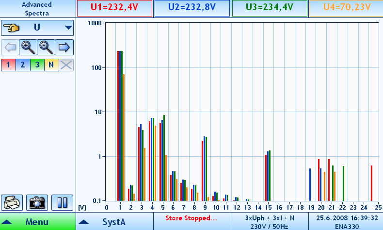
Although even small deviations from the pure sinus waveform appear insignificant, they are not. Because they can hardly be seen or detected in the time domain, we illustrate the signals in the frequency domain to see the effects.
What we actually see here are integer multiples of the fundamental frequency of 50Hz for all three phases – so the 3rd, 5th, 7th Harmonics actually inform us about the order of the harmonic.
Reasons for non-linearity
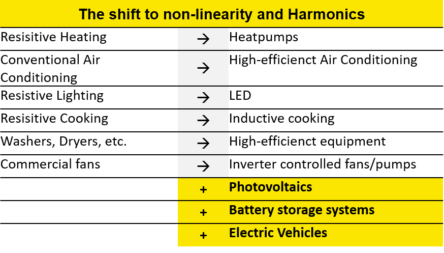
Harmonics generally exist due to non-linearity on both sides of source and load, or generation and consumption. On the one hand, engineers certainly do their best to design and produce electrical equipment on the highest (symmetry) levels. However, Harmonics remind us that the complexity of the whole power system still brings out minor non-linear relations by default. On the other hand, the major reason for the emergence of Harmonics is the Power-Electronics era we live in today. With the increasing replacement of linear loads by non-linear ones, Harmonics became a focal point of Power Quality Analysis.
Effects of Harmonics
Harmonics don’t only influence the signal shapes, but operation and the life span of electrical devices and equipment. Harmonic frequencies in motors and generators can result a various mechanical phenomena that all lead to efficiency reduction. Among these are higher audible noise, faster ageing of the shaft, insulation and mechanical parts. Furthermore pulsating or reduced torque as well as increased heat development.
Sidebands, Half-bands and Interharmonics
In order to sum up a minimal yet clearly defined frequency range around a specific harmonic, sidebands and half-bands exist. They define what +/- area belongs to, let’s say, the 5th Harmonic of 250Hz. For example, a single sideband leads to the area of 245-255Hz, while one sideband generally regards the square root of half amplitude between 240-260Hz. Last but not least, Intraharmonics define the frequencies that are not within the harmonic definitions. For further information we would like to refer you to the specifics in the IEC 61000-4-7.
3 – IEEE 519
By establishing a standard and goals for the design of electrical systems, the IEEE 519 is the focal point of this article. The goals include both linear and non-linear loads and aim to minimize interference between electrical equipment.
[..] The limits in this standard represent a shared responsibility for harmonic control between system owners or operators and users. Users produce harmonic currents that flow through the system owner’s or operator’s system which lead to voltage harmonics in the voltages supplied to other users. [..] Limits are provided to reduce the potential negative effects on user and system equipment.
Institute of Electrical and Electronics Engineers
New and updated definitions – At a glance
- Point of Common Coupling (PCC): As the standard lays out, it is the interface between sources and loads. Observing the design goals will minimize interference between electrical equipment.
- Maximum Demand Load Current: Taking into account the maximum load on the PCC, which is the average sums of the previous 12 months.
- Total Demand Distortion (TDD): A %-value that relates the harmonic RMS parts to the maximum demand current. It is important to note that the standard thereby specifies the Harmonics parts up to the 50th order and explicitly excludes interharmonics.
- Total Harmonic Distortion (THD): Another percentage-value and the sum of all harmonics in relation to the fundamental.
Summing up, our solutions and FFT analysis provide amplitude and phase spectra, thus the U, I, P, Q spectra. In power spectra, the power flow on a particular harmonic helps to identify sources of disturbances.
Observation periods
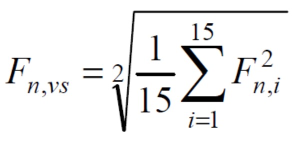
Very short time harmonic values are assessed over a 3-second interval based on an aggregation of 15 consecutive 12 (10) cycle windows for 60 (50) Hz power systems.
Individual frequency components are aggregated based on an RMS calculation with F representing voltage (V) or current (I), n representing the harmonic order, and i as a simple counter. The subscript vs is used to denote “very short.” In all cases, F represents RMS values.
Observation period
- 24 hours
- The 99th percentile value (i.e., the value that is exceeded for 1% of the measurement period) should be calculated for each 24-hour period for comparison with the recommend limits in Clause 5.
- Applied to both voltage and current harmonics.
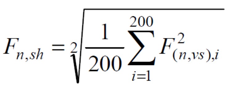
Short time harmonic values are assessed over a 10-minute interval based on an aggregation of 200 consecutive very short time values for a specific frequency component.
The 200 values are aggregated based on an RMS calculation with the subscript used to denote “short”.
Observation period
- 7-day period (1 week)
- The 95thand 99thpercentile values (i.e., those values that are exceeded for 5% and 1% of the measurement period) should be calculated for each 7-day period for comparison with the recommended limits in Clause 5.
- These statistics should be used for both voltage and current harmonics with the exception that the 99th percentile short time value is not recommended for use with voltage harmonics.
- Current harmonics evaluate based on 95th and 99th-percentile.
- Voltage harmonics evaluate based on 95th-percentile only.
Limits for Voltage Distortion

Limits for Current Distortion
Newly defined limits based on 3 percentile limits:
- Daily 99th-percentile very short time (3 s) harmonic currents should be less than 2.0 times the values given in the Tables.
- Weekly 99th percentile short time (10 min) harmonic currents should be less than 1.5 times the values given in Tables.
- Weekly 95th percentile short time (10 min) harmonic currents should be less than the values given in Tables.


- a Even harmonics are limited to 25% of the odd harmonic limits above
- b Current distortions that result in a dc offset, e.g., half-wave converters, are not allowed
- c All power generation equipment is limited to these vales of current distortion, regardless of actual ISC/IL.
- ISC = maximum short circuit current at PCC
- IL = maximum demand load current (fundamental frequency component) at PCC
Challenges for most PQ equipment
Following the framework of the IEEE 519 we now leave the world of standards and come back to our initial situation. In which we want to make reliable statements about the grid and possible harmonic disturbances. Ideally, we are only one set-up and one report away from that. Well, ideally.
Connecting to the previous chapter about limitations – are there any to get to a sound report? As you might expect, there is an answer to the question. Although the observation period according to the IEEE 519 is indeed very long – many measuring solutions don’t have the required memory space for even a week of data. For a rough estimation we would state the required memory between 200-500MB for a single week – depending on the set-up. The limited instruments help themselves by building average values that find their way into Reports. For us this is a major flaw we don’t need to face with today’s possibilities.
IEEE 519 – Harmonic Compliance Report
Summing up this chapter about the IEEE 519, we show you how the Harmonic Compliance Report looks like for our customers. As you can see in the schematic illustration, the limits and eventual excesses are clearly stated according to the standard. Needless to say, the list continues up to the 50th order, but we are sure you get the point. Anyway, in the next chapter you will see that NEO Messtechnik solutions don’t even stop at the 50th Harmonic..

Green = Harmony
Red = Harmonics violation
4 – Higher Frequencies and Supraharmonics
Limits of the IEEE 519
Harmonics are regarded as basic and well covered topic in the Power Quality industry. But on this occasion we would like to point out that it is not like that after all. Let’s find out why.
So far, we have only talked about frequency parts of up to the 50th order. Although the specs of many PQ Analyser and Monitoring solutions try to convince you otherwise – we can certainly assure you that Power Quality doesn’t stop right there. Even more so, this is where the real challenges begin. Let’s refresh with a basic rule of electric measurement technology. The sampling frequency should be, at least, twice the value of the expected measurement signal.
By following the IEEE 519, analysing up to the 50th has always been on the safe side of the whole. But if you limit yourself to this observation window, you miss the area beyond 2kHz.

Where the fun (for our PQA 8000H) begins ..
No standards. No problems?
There is a reason why we actively write about these higher frequencies in greater detail. The increase of Power electronics and inverters will further increases the measurement demand of Higher Frequencies and Supraharmonics. Emissions in the frequency range from 9 kHz to 150 kHz are sources of electromagnetic interference to various electric equipment in the grid. You can find a more in-depth article about Supraharmonics and its implications in our AppNote.

More in-depth information
Easy accessible in your Download Area. Sign up!
5 – Harmonic Summary and Peaceful Outlook
We did not only cover the topic of Harmonics and the essence of the IEEE 519, but expanded our horizon beyond the 50th Harmonic order. Non-linearity and power electronics will further drive research and co-operation of universities and PQ experts like us, if you excuse our humbly self-attribution. Following to this article we will continue with Chapter 4, more PQ parameters and the EN 50160.




0 Kommentare