Flicker, RVC & Symmetrical Components Erklärt – Kapitel 4
- Gepostet von Neo Messtechnik
- Am 4. März 2021
- 0 Kommentare
Das Stromnetz und die elektrische Spannung sind nicht immer so stabil, wie man denkt. Deshalb sind Flicker, schnelle Spannungsänderungen (Rapid Voltage Changes) und symmetrische Komponenten zentrale Parameter zur Beurteilung der Netzqualität. Erfahren Sie, wie wir mit Hilfe der symmetrischen Komponenten zur Symmetrie und allen Netzparametern zurückfinden!
Inhaltsverzeichnis
1 – Überblick
Willkommen zu Kapitel 4 unserer Multipart-Serie
Mit dem heutigen Artikel nähern wir uns in großen Schritten dem vorläufigen Ende dieser Serie.
- Netzqualitätsmessung der Zukunft
- Grundlagen-Wissen
- Elektrische Leistung & Energie
- IEEE 519 & Harmonische
2 – Flicker
Definition
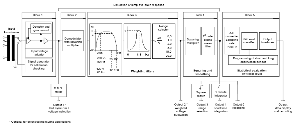
Flicker is a visible change in lamp brightness due to voltage fluctuations. These changes emerge in power grids with a low short-circuit resistance and as response to rapid connection or separation of loads. A high level is considered to be harmful and irritating to people. While we are focusing on how to measure Flicker according to the standards, under this link you can find a closer look on the implications on the human eye.
IEC 61000-4-15 Flicker meter
The standard provides understanding for the correct determination of flicker level perception for all practical voltage fluctuation waveforms. Based on the simulation of the lamp-eye-brain chain, the flicker signal is statistically evaluated and calculated in the normed parameters. Creating a reference signal in Block 1, the next three Blocks simulate the human perception of it. The Flicker parameters are calculated in Block 5.

Definition of Flicker values
| Flicker | Description |
|---|---|
| Pinst | Instantaneous Flicker Sensation from IEC 61000-4-15 |
| Pst | Short Term Flicker every 10 minutes for voltage input signals |
| Plt | Long Term Flicker every 2 hours from the previous 12 Pst values |
| I_Pinst | Instantaneous Flicker Sensation from IEC 61000-4-15 for current |
| I_Pst | Short Term Flicker current |
| I_Plt | Long Term Flicker current |
| I_Pinst_L1_30, I_Pst_L1_30, I_Plt_L1_30 | Flicker values for a specific phase angle |
Current Flicker Definition
IEC 61400-21 defines the calculation of Flicker emission, caused by renewables like wind power plants. Producers as well as consumers are the originators and thereby effecting the power grid. The internal voltage drip in the following picture is calculated on the basis of the grid impedance and the current flow.

3 – Rapid Voltage Changes (RVC)
Definition of RVC
- The EN 50160 defines RVCs as: “A single rapid variation of the rms value of a voltage between two consecutive levels which are sustained for definite but unspecified durations.”
- The IEC 61000-3-3 defines voltage change characteristic as following: “the time function of the RMS voltage change is evaluated as a single value for each successive half period between the zero-crossings of the source voltage and the time intervals in which the voltage is in a steady-state condition for at least 1 s.”
- In IEC61000-4-30, rapid voltage changes are defined as: A quick transition in RMS voltage between two steady-state conditions. To measure rapid voltage change, thresholds must be defined for each of the following minimum ..
- rate of change
- duration of the steady-state conditions
- difference in voltage between the two steady-state conditions
- plus Steadiness of the steady- state conditions
The voltage during a rapid voltage change must not exceed the voltage dip and/or the voltage swell threshold. Otherwise, it would count as a voltage dip or swell. The characteristic parameter of rapid voltage change is the difference between the steady state value reached after the change and the initial steady-state value.

More in-depth information
Easy accessible in your Download Area. Sign up!
4 – Symmetrical Components
What is Unbalance?

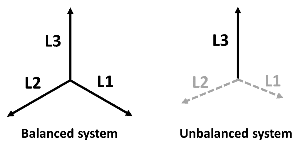
Disturbances or short circuits among others result in an unbalanced system. The concept of symmetrical components enables the transformation of any desired unbalanced 3-phase system (unbalanced electric grid system influenced by a number of factors) into three separated symmetrical components.

Zero-sequence
In a symmetrical system, without any disturbances, the phase voltages sum up to zero.
U_L1 + U_L2 + U_L3 = 0
This symmetrical state never appears in real-life grids. The zero sequence results due to disturbances and from current flow in the neutral line U_N. The following voltage difference determines said current flow:
U_L1 + U_L2 + U_L3 = ⍙u
This voltage difference divided by three is the zero-sequence system:
U_0 = 1/3 * ⍙u = u10 = u20 = u30
- The zero sequence has the same amplitude and phase for all of three phases (u10, u20, u30).
- This is the reason you usually find only one value, U_0, in literature or within our software.
- The calculation of the current zero-sequence is analogue to this procedure.
- Multiplying the zero-sequence system of the current by 3 (3 x I_0) equals the current over the neutral line U_N.
Positive-sequence
This part rotates in the same direction as the given system (e.g. grid or electric motor/generator) and is a symmetric system for itself. This means the amplitude for all three positive phases is the same and only having a 120° phase shift to each other. This is where the unit vector a comes in to simplify the formulas.
Negative-sequence
This part rotates in the opposite direction as the real system (e.g. grid or electric motor/generator) and is a symmetric system for itself. Like the positive system, the phase values are the same with a 120° phase shift to each other.
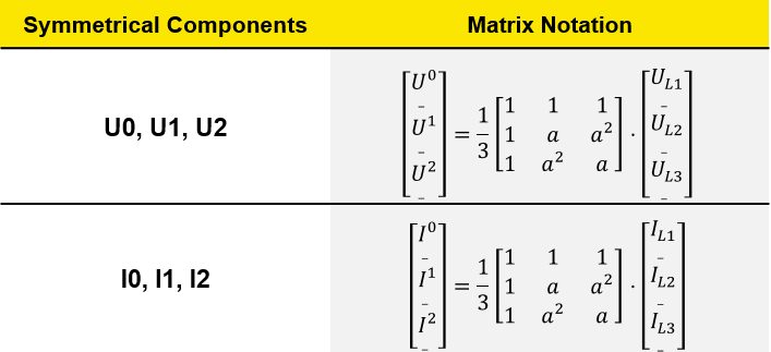
Matrix of symmetrical components
The three symmetrical components for voltage and current in matrix form give a clear overview on the whole system and the importance of the operator a.

Calculation of phase voltages or currents
By using the formulas from above it is possible to calculate the phase voltages and current flow of the 3-phase system with the help of the symmetrical components.
IEC 61400-21 Annex C
According to Annex C of IEC 61400-21, the Fourier coefficients (cos- and sin-parts) of both measured phase voltages and currents are calculated over one fundamental cycle T. Using NEO PQ solutions allows you to easily access all the parameters you need for in-depth analysis. This includes all RMS values for every active, reactive and apparent part of the three symmetrical systems. Fore more information about how the calculation within the software, drop us a line on LinkedIn!
5 – Voltage Events & Flagging
Voltage Dips, Swells & Interruptions
Für Spannungseinbrüche, -überhöhungen und -unterbrechungen muss die Effektivspannung über 1 Zyklus (auf Basis einer gleitenden ½-Periodenwert-Schätzung), beginnend bei einem fundamentalen Nulldurchgang, ausgewertet und alle Halbzyklen aufgefrischt werden. Ereignisse werden erkannt, wenn die Spannung den vordefinierten Bereich verlässt (üblicherweise ±10% von Un). In Anlehnung an die IEC61000-4-30 werden einphasige oder dreiphasige Ereignisse entsprechend der Abbildung unterschiedlich ausgewertet.

Flagging
Voltage monitor data must be stored as ‘flagged’. During a dip, swell, or interruption, the measurement algorithm for other parameters (for example, frequency measurement) might produce a unreliable value. The flagging concept therefore avoids counting a single event more than once in different parameters (for example, counting a single dip as both a dip and a frequency variation) and indicates that an aggregated value might be unreliable.
Flagging is only triggered by dips, swells, and interruptions. The detection of dips and swells is dependent on the threshold selected by the user, and this selection will influence which data has been ‘flagged.’
6 – Steady Summary. Symmetrical Outlook!
Within this last article we have learned the implications of varying voltage levels in the power grid. Both Flicker and Rapid Voltage Changes are central parameters for the EN 50160 report that will soon be our next focus point in Chapter 5.
Literatur
Chapter 5 – coming soon


