Measurements in all voltage levels up to 150 kHz – is that possible?
- Posted by Neo Messtechnik
- On 7. February 2023
- 0 Comments
A reliable energy supply has now become an important location factor for many companies. While in the past power failures and voltage fluctuations were among the most important parameters of supply quality, votlage transients or votlage harmonics are becoming increasingly important. This is mainly due to the ever increasing number of non-linear consumers and many decentrally connected regererative energy sources.
To ensure uniform standards for electrical power supply in Europe, the minimum requirements for voltage quality are defined in a European standard. This is EN 50160, which is entitled “Characteristics of votlage in public electricity supply networks”. This standard is to be understood as a product standard for electrical energy and for this reason is also used in electricity supply contracts as the applicable product standard. In February 2014, the Federal Court of Justice made it unequivocally clear that electricity is also subject to the Product Liability Act. This means that the distribution system operator is liable for damage to the electrical consumers that is caused by a defective voltage quality on the part of the distribuation system operator.
For this reason, many meter manufacturers now offer meters that prepare automated quality reports in accordance with EN 50160. Digital meters also increasingly offer power quality functions in accordance with EN 50160. While the measuring devices can process the voltage directly in the low voltage, voltage transformers or votlage sensors are required in the medium and high voltage. In most cases, the voltage trasformers installed do not usually give ay indication on the rating plate of teh transmission behavior at higher frequencies. The devices are only specified for the 50 Hz fundamental frequency of the networks. However, measurements according to EN 50160 require a frequency range up to 2 kHz.
Table of Contents
Suitability of existing Devices for measurements up to 2 kHz
In the following, the question will be investigated whether the existing devices are suitable for measurements up to 2 kHz. With the isntalled voltage transformers are often inductive transformers, which work according to the transformer principle. In detail the primary coil not only consists of inductively acting copper windings, but there are also capacitancces due to the individuial layers insulated from each other. the capacitances between the indiviual windings also contribute to the total capacitance of the primary coil. This results in a osciallting circuit of inductance, capacitance and ohmlic resistance, which must also have a corresponding resonant frequency.
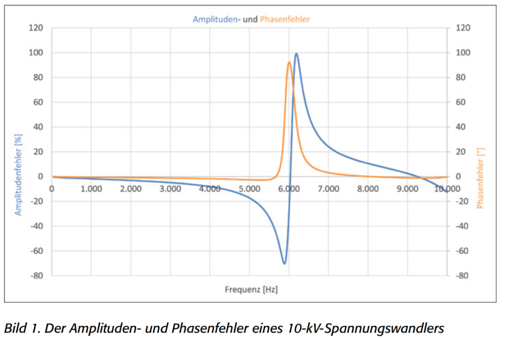
To find this resonant frequency a commercially available 10-kV voltage transformer is measured using the “frequency sweep method” with 6400 measuring points up to 10 kHz. The measurement setup is based on the recommendations of hte technical report IEC TR 61869-103.
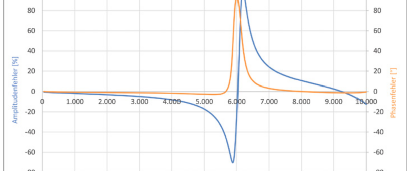
A resoncane point can be detected at about 6 kHz (Fig. 1). While the transducer transmits the primary signal acceptably up to about 5 kHz, there is an amplitude error of about 100% and a phase error of 90° at about 6 kHz. A reliable PQ analysis up to e.g. 2 kHz is possible wothout restrictions, but what about converters in other voltage levels?
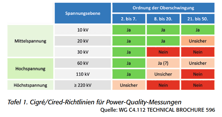
A contribution of the technical-scientific organization Cigré/Cired offers good assistance to the metering point operators. Here, a guidline for power quality measurements was published, which provides a meaningful table regarding the frequency transfer behaviour of voltage transformers.
it can be seen that generally 10-kV votlage transformers up to the 50th harmonic (2.5 kHz) can be used for PQ measurements. In the 20-kV range, however, according to Table 1, devices have already been found which do not provide reliable measured values on the secondary side from the 21st harmonic. in the 30-kV range, a blanket approval has been given only up to the 7th harmonic. It must be stated that only 10.kV voltage transformers in existing plants can be used for reliable EN 50160 measruements. In the 20 kV and 30 kV voltage levels, information mus be privided by the transfomer manufacturer.
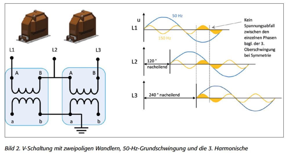
The converters examined here are exclusively single-pole devices. Two-pole voltage transformers, whcih can still be found in older plants, cannot be used for analysis of harmonics. This is due to the voltage measruement between the conductors. Despite the 120° phase offset of the 50 Hz conductor voltages, the amplitude values of the superimposed 3rd harmonic are not offset and thus cannot generate a voltage difference between the conductors. (Fig. 2) This is generally true for all harmonics divisible by three. As a result, the THDu is reduced by the values of the voltage harmonics divisible by three (3, 6, 9, etc.)
Measurements up to 2 kHz still sufficient?
Fruthermore, the question arises wheather measurements up to 2 kHz are still sufficient. In the current DIN EN 61000-2-2 already specifies limit vlaues for voltages up to 150 kHz. Although EN 50160, which is cited in electricity supply contracts, has been updated in 2020, limit vlaues beyond 2 kHz have not yet been defined as binding. Thus, voltage measurement up to 2 kHz is sufficient for determining the quality of the electrical energy. In the area of feed-in systems, frequency-optimized voltage transformers up to 9 kHz are already used on the basis of the technical connection rules (e.g. VDE-AR-N 4110). However, al largefrequency range is not possible with inductive voltage transformers.
An alternative is offered by sensors which are designed as RC dividers in the medium and high voltage. in the medium voltage range, RC dividers are already used as terminating inserts for T-connectors or as air-insulated supports (Fig. 3). In order to obtain a good frequency response over the required range, the following must be met:
R1 x C1 = R2 x C2
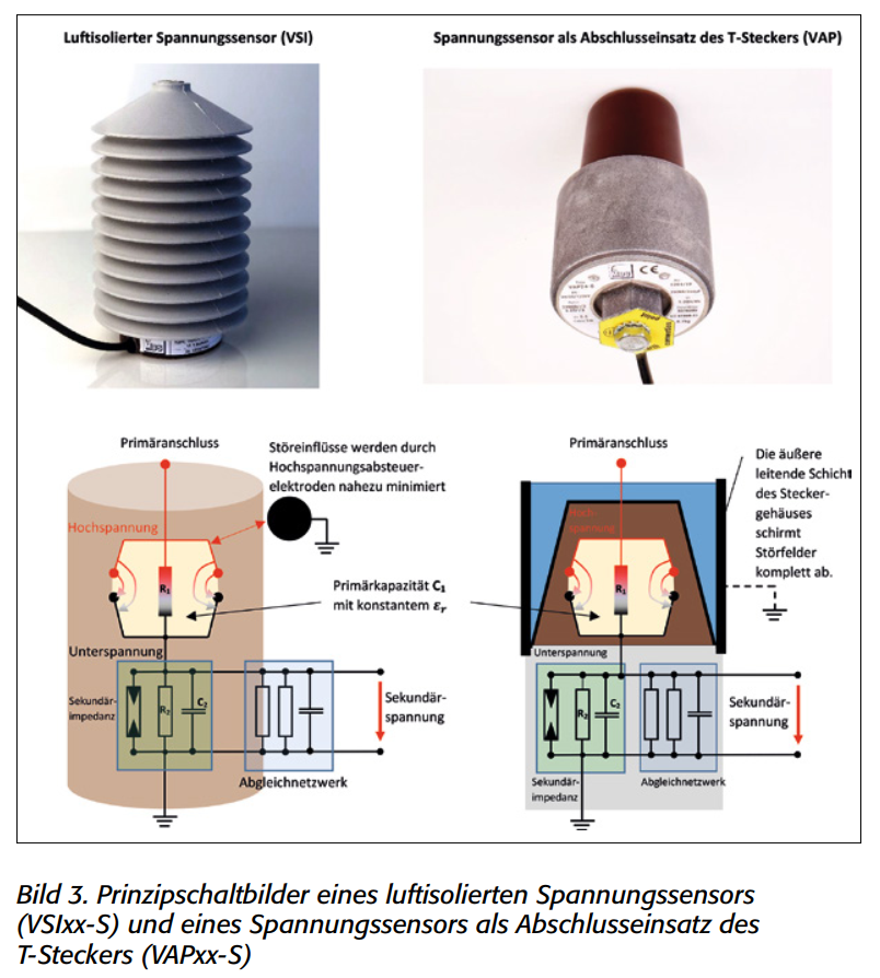
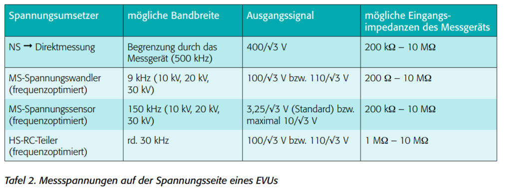
Meaurements have shown that conventional “50 Hz RC dividers” are often not suitable for broadband measurements. Instead, the devices must be optimized for higher-frequency applications. In medium voltage, devices up to 150 kHz are already available. In high voltage, RC dividers up to 30 kHz are currently available on the market. If the utility uses MS sensors for PQ measurements, the smaller secondary signals should be taken into account. In contrast to the traditionally inductive voltage transformers with 100/√3 V, the voltage sensors only output a small signal up to a maximum of 10/√3 V. In the low voltage, the voltage signals are tapped directly from the live conductors. Frequency-optimized high voltage transformers, which are designed as RC dividers, usually provide 100/√3 V like the conventional votlage transformers.
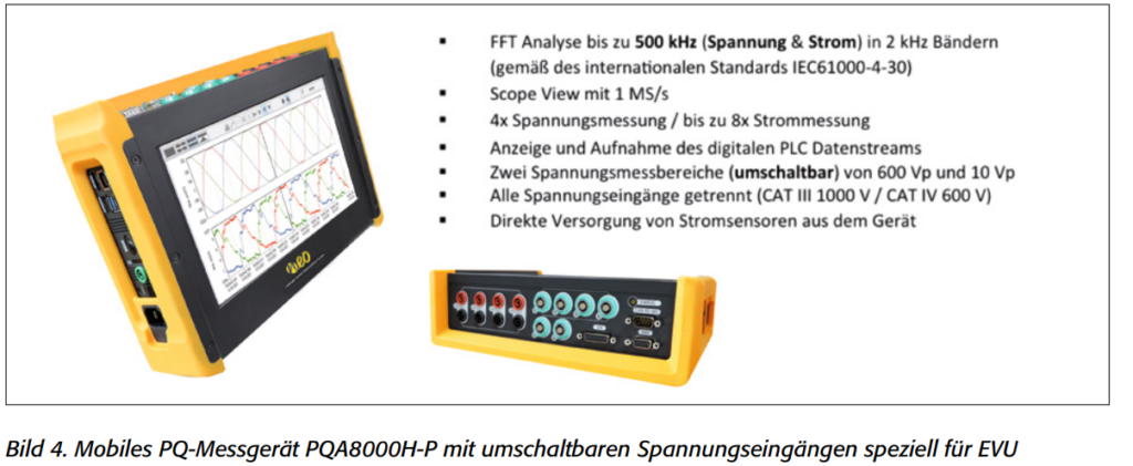
This results in different secondary voltages in the environment of a utility company (Table 2). In order to be able to guarantee sufficient resolution and accuracy, a mobile PQ measuring device should be designed for these different measuring voltages. The only mobile measuring device that meets these requirements is the PQA 8000H-P from Neo Messtechnik (Fig. 4). Here there are switchable voltage inputs for 600 Vp and 10 Vp or 20 Vp. With this option it is possible for utility companies to carry out high-quality PQ measurements in various voltage levels.
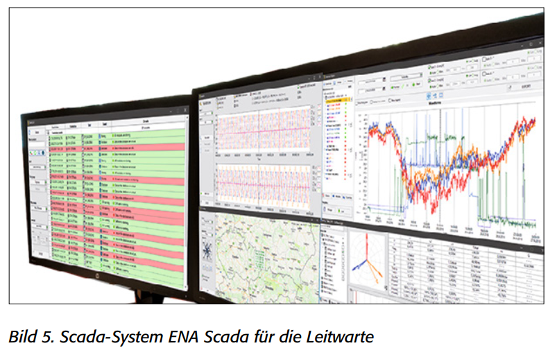
The input impedance of the voltage channels is 10 MΩ || 2 pF. Conventional voltage transformers in medium voltage are specified in terms of class accuracy with a burden power in VA. Values between 5 VA and 20 VA are common. The class noted on the rating plate applies to 25 % to 100 % of this power. The power requirement of the mobile PQ instrument is infinitesimal at the usual secondary output voltage of 100/√3 V. The measuring device can therefore be operated in parallel to the connected measuring devices without any effect on the accuracy. The situation is different for the sensors in the medium and high voltage. Here, the RC dividers are precisely calibrated to the load resistance. In the high voltage, therefore, an extra terminal is often designed for the PQ measuring device. In medium voltage, the sensor must be precisely matched to the measuring device. However, measuring devices can also be operated in parallel here. By using parallel additional resistors, the PQ meter can be simulated when not in use. When using several measuring devices measuring stations, a convenient connection to the ENA-Scada System is possible (Fig. 5).
Summary
It can be stated that by using ohmic-capacitive voltage sensors in the medium votlage in conjuction with a switchable mobile PQ-Analyzer, measurements up to 150 kHz can also be performed. RC dividers in the high voltage currently cover a measurement range of up to 30 kHz. From a technical point of view, there is nothing to prevent the limits from the current IEC 61000-2-2 being adopted in EN 50160 for low and medium voltage.
Wrapping up
Where can I get more information?


0 Comments