Understanding IEC 61000-4-30 Class A Power Quality Analyzer
- Posted by Neo Messtechnik
- On 3. May 2021
- 0 Comments
The IEC 61000-4-30 Class A Ed. 3 defines the methods for measurement and interpretation of results for power quality parameters in AC power supply systems with a declared fundamental frequency of 50 Hz or 60 Hz. What does that mean? Let’s take a closer look on the Class A classification and how it impacts your decision for a power quality analyzer.
Table of Contents
Introduction
Whether it is for your own interest, regulatory reasons or customer complaints – our main goal is to gain knowledge on how to detect Power Quality issues. Furthermore, which PQ Monitoring systems fit these needs and regulatory requirements. Serving as first step we will talk about the standard that defines how to correctly measure PQ parameters. First introduced in 2003, it’s latest version published in 2015 – you may already nod your head – we are certainly talking about the IEC 61000-4-30: Ed. 3 Testing and measurement techniques – Power quality measurement methods.
No standards, no problems?
Although it seems like a long time ago, Power Quality Assessments lacked standards and comparable limits. Reports and hence Power Quality level depended on your PQ instrument, which wasn’t a satisfying situation for engineers.
What is the IEC 61000-4-30 Ed. 3 standard?
It defines the methods for measurement and interpretation of results for power quality parameters in a.c. power supply systems with a declared fundamental frequency of 50 Hz or 60 Hz.
International Electrotechnical Commission
In short, independently of the PQ instrument of your choice, the IEC 61000-4-30 established a common framework for PQ Monitoring systems to obtain reliable and comparable results.
IEC 61000-4-30 Measurement Classes
What does Class A mean according to the IEC 61000-4-30?
The IEC 61000-4-30 Class A defines measurement methods, time aggregation and specifics about accuracy, bandwidth, limits and evaluation of various PQ parameters. By choosing a Class A complying instrument, you make the first important step for getting reliable results according to the IEC 61000-4-30. It standardizes measurements of the following parameters
With the third edition the standard was extended by
Measurement uncertainty
Measurement engineers rely on the equipment they are using, and the accuracy it offers. The measurement uncertainty for Class A certified devices is defined at 0.1% of the input voltage. This sets a common level allowing users to get compliant measurement results and compare those of instruments from different companies.
Voltage flagging
Getting reliable results from your power quality measurement and analysis setup is central even throughout voltage dips, swells or interruptions. With the help of the flagging concept single events do not count for multiple occurrences. For example, a single dip doesn’t count as both frequency variation and voltage dip. What the flag actually indicates is the possibility of unreliability.
For voltage dips, swells and interruptions, the RMS voltage must be evaluated over 1 cycle (on base of sliding ½ period values estimation), commencing at a fundamental zero crossing, and refreshed every half-cycle. Events are detected if the voltage leaves the pre-defined range (usually ±10% of Un). By following IEC61000-4-30 according to the illustration, single phase or three-phase events are evaluated in a different way.

Time aggregation of PQ data & Frequency determination
The IEC 61000-4-30 defines the time windows for parameter magnitudes (supply voltage, harmonics, inter-harmonics and unbalance). It is a 10 cycle time interval for a 50 Hz power system or 12-cycle time interval for a 60 Hz power system. Furthermore, aggregations of the measured time intervals takes place over three different time intervals:
By the emphasis on the ongoing monitoring process, questions about data storing and data handling automatically emerge and challenge monitoring systems to varying degrees.
Requirements of 4 differential voltage and 4 differential current channels
While single-ended amplifiers are easy to use due as their second pin is connected to ground, they are only suitable for measuring floating voltage sources and thereby have two disadvantages – the influence of ground loops and the missing isolation. Unfortunately some PQ instruments only have single-ended amplifiers only. In contrast to them, differential amplifiers using inputs separated from ground avoid the aforementioned ground loops, although deal with the problem of common mode voltage.
Isolated amplifiers eliminate all these disadvantages like ground loops, common mode voltage as they are isolated from the housing and the main board of the measuring device and are therefore a safe and reliable solution handling voltage peaks, faults and other disturbances. All High-Voltage inputs of the NEO Instruments are isolated. Current Inputs (via Low-Voltage inputs) are usually non-isolated, as isolation is provided by the used current sensors.
Class A ++ Power Quality Analyser
We cannot end this article about the IEC 61000-4-30 Ed. A Class A without showing you what a Power Quality Analyser can look like that goes well beyond the norm – Class A ++.

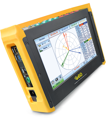
PQA 8000H
All-In-One. 1MS/s. Multi-Touch. 4h mobile operation. The reference instrument on the market.


0 Comments