Current harmonic measurement at the grid connection point of the power generation plant
- Posted by Neo Messtechnik
- On 2. May 2023
- 0 Comments
In Germany, the respective technical rules for the connection of customer installations to the low-, medium-, high- and extra-high-voltage grid and their operation have been standardized throughout the country in recent years.1 All these rules describe the measurement of current harmonics up to 9 kHz. The respective maximum levels are calculated, among other things, from the connected load.
Currently, the majority of generation plants, such as wind energy or photovoltaic plants, are connected to the power supply grid using various converter technologies. While in photovoltaic systems the directly generated direct current feeds an inverter, in a wind energy system the three-phase alternating current is first rectified by the generator. This is followed in turn by conversion to three-phase alternating current.

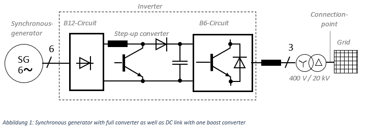
In many of the currently installed plants, a synchronous generator is combined with an inverter. In the first step, the output voltage of the synchronous generator is rectified. Bridge circuits (B) are often used for this purpose. The following figure specifies the number of semiconductor switches used. In the example above, the synchronous generator supplies a six-phase voltage system. This is then rectified with a B12 diode bridge circuit. The voltage level in the DC link is then raised by a boost converter. After the DC link, the inverter generates a grid-compliant three-phase system in B6 circuitry. In the majority of cases, the inverter is based on pulse width modulation. This is a control method for self-controlled converters and inverters. This method, which is frequently used for generation units, replicates the 50 Hz voltage waveform to be fed in by pulsing the DC voltage from the DC link (wind turbine) or the DC source (photovoltaic system). The synthetically generated sinusoidal oscillation is not perfect, so that harmonics are always generated as well. The proportion of harmonics correlates, among other things, with the switching frequency of the inverter. A higher switching frequency can reduce the distortions of the sinusoidal oscillations. At the same time, however, a higher switching frequency increases the losses in the semiconductor modules used in the inverter. The choke coil at the output of the inverter is used to smooth the current. Currently, the switching frequencies for wind turbines are between 2 and 4 kHz. Inverters in the photovoltaic sector are mostly between 4 and 20 kHz due to the lower rated power.
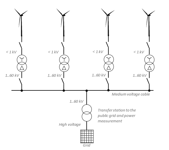
The inductor on the output side as in figure 1 of the inverter is used for current smoothing. To avoid transmission losses in the cables, the output voltage is transformed up to 20 kV. Although wind turbines can also be designed as individual plants, they are usually connected together in parks and then coupled to the public grid at the high or extra-high voltage level.
In general, inverters are to be regarded as interference emitters2, since high-frequency components are generated by the steep current rises and transient processes. For this reason, the voltage output signal is smoothed by filter measures in order to increase the electromagnetic compatibility. Higher interference levels can be caused by defective modules or if the turbines are only operated in the partial load range. Even if the type of turbine used in the wind farm has received plant certification in accredited testing laboratories in accordance with the Technical Guideline Part 33 (TR3) applicable to renewable energies, higher current harmonics of up to 9 kHz may well be measured at the grid connection point than are permitted in the applicable application rules. If this is the case, harmonic filters are installed at the grid-connection point in order to be able to comply with the defined limit values.4 Reliable measured values up to 9 kHz are the basic requirement here. The application rules therefore specify class A (A=Advanced) power quality analyzers in accordance with the IEC 61000-4-30 (Edition 3) standard. The accuracy defined here is less than 0.1 % for the voltage and current channels, for example. In principle, the measurement data of these devices can be cited as evidence in the event of legal disputes or contractual disputes. In the case of class S power quality analyzers (S=Survey), the data and recorded events can only be recorded qualitatively and can only be used for internal statistics.
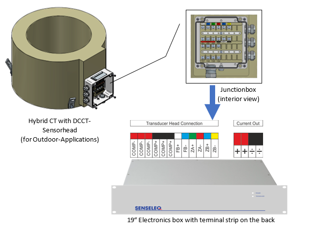
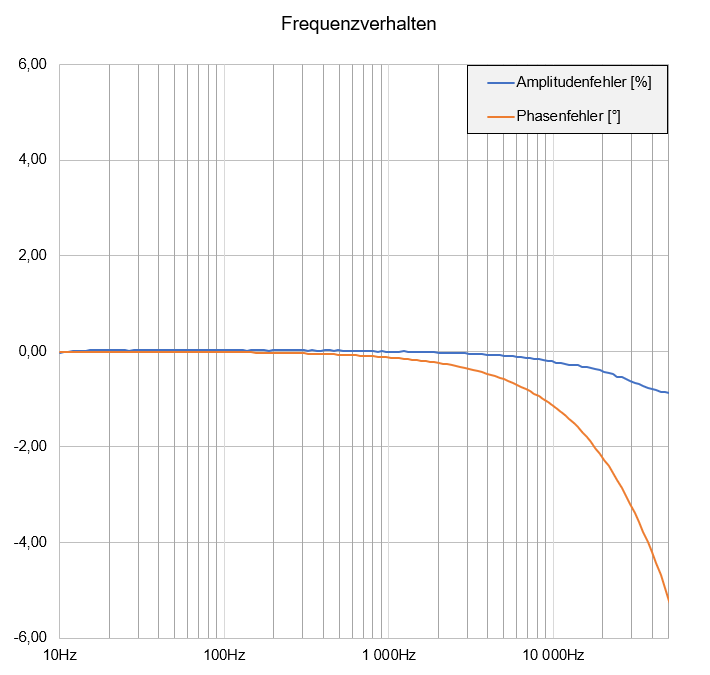
In addition to the analyzers, the current sensors must also have a high accuracy of up to 9 kHz. However, certified accuracy measurements in accordance with IEC 17025 are only offered up to 60 Hz by relevant test laboratories in Europe. A measurement standard up to 9 kHz is not yet available worldwide. Accordingly, to date, only test results from manufacturers or laboratories are available that cannot be traced back to a measurement standard. In 2019, under the leadership of PTB, a first document has been published on how an accurate and test setup can look like in order to obtain reproducible measurement results.5 The work was done in the European project Future Grid II (Metrology for the next-generation digital substation instrumentation).6 Among other things, high-precision fluxgate current sensors from Danisense were used. The same technology is now found in cast-resin encapsulated conversion transducers made by Senseleq, a joint venture between Eleq, a Dutch transducer manufacturer, and Danisense, a Danish manufacturer of high-precision current sensors (zero-flux principle). These fluxgate current sensors can be installed on transformer bushings or switchgear and provide highly accurate readings from DC to the three-digit kHz range. Thus, even low-frequency (< 50 Hz) disturbances can be reliably detected, as mentioned in the application rules, which are not detectable with pure AC sensors or lead to malfunctions due to saturation phenomena.
The measurement proof for the analysis for higher frequency components looks as follows for a 2,500/1 A Senseleq current transformer.
While the defined maximum levels up to 9 kHz are a good aid for network operators to be able to protect the network against interference, problems at the network connection point or with neighboring systems above 9 kHz cannot always be ruled out. For example, multiples of the clock frequency with corresponding sidebands are formed in addition to the clock frequency. This phenomenon is described by the following formula.
f = n × fT ± 2 × n × f1
f = frequency in the grid
n = multiplier (1;2;3;…)
fT = clock frequency of the power electronics
f1 = fundamental frequency (50 Hz)
If an inverter is now clocked at 4 kHz, attenuated amplitudes are also to be expected at 8, 16 and 20 kHz with the corresponding sidebands.
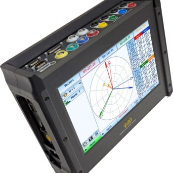
Power quality analyzers with sampling rates of at least 300 kHz at the current and voltage inputs are therefore recommended in order to cover the entire power quality range up to 150 kHz. For example, power quality analyzers from Neo Messtechnik GmbH in Austria have proven their worth. In addition to the high sampling rate of 1 Ms/s, smaller amplitudes at higher frequencies are still detectable due to a very good signal-to-noise ratio.
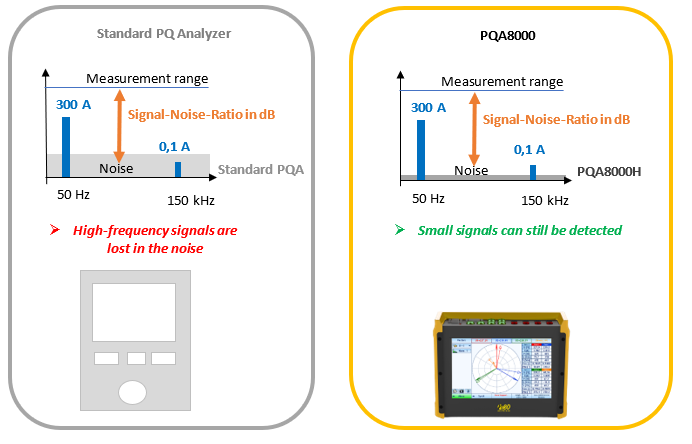
In addition, voltage sensors for medium voltage with small signal outputs can be connected to the device via switchable voltage inputs (600 Vp and 10 Vp). Current or voltage outputs are available for the Senseleq current sensors. Voltage outputs can be connected directly to the meter. For current signals, low inductance measurement shunts are introduced into the secondary output.
Some network operators have already updated their technical connection conditions (TAB) in Germany and thus impose further investments on the operator of the power generation plant with regard to the measuring equipment in the transfer station. A financial burden on the network operator can thus be avoided, unlike in the case of a connection in the low-voltage range. The operator of the plant is also obliged to send a message to the network operator in the event of a violation of the maximum levels in accordance with the standard.
1 VDE-AR-N 4100 Anwendungsregel:2019-04 (Niederspannung); VDE-AR-N 4110 Anwendungsregel:2018-11 (Mittelspannung); VDE-AR-N 4120 Anwendungsregel:2018-11 (Hochspannung); VDE-AR-N 4130 Anwendungsregel:2018-11 (Höchstspannung)
2 Detlef Schulz (2004): Netzrückwirkungen – Theorie, Simulation, Messung und Bewertung, Berlin und Offenbach: VDE-Verlag
3 TR 3 – Bestimmung der elektrischen Eigenschaften von Erzeugungseinheiten und -anlagen, Speicher sowie für deren Komponenten am Mittel-, Hoch- und Höchstspannungsnetz
5 https://oar.ptb.de/resources/show/10.7795/EMPIR.17IND06.CA.20191122
Wrapping up
Where can I get more information?


